Using the Gear Definition Dialog
Use the Gear Definition dialog to do either of the following:
• Define an AxiGroove that is not represented in your CAD model. See Defining AxiGrooves.
• Edit the properties of an AxiGroove that aPriori has extracted from your CAD model. See Overriding AxiGroove Properties.
For each field of the Gear Definition dialog, enter a value in the right-hand column (labelled Override Value), if you do not want to use the default provided in the left-hand column (labelled aPriori Default). The dialog includes only those fields that are relevant to the type of gear currently specified in the Gear Type field.
Following are the fields that can appear in the dialog (each field is described in detail below):
Module
Gear Type
aPriori supports several types of AxiGrooves, including these types of gears:
• Internal Spur
• External Spur
• Internal Helical
• External Helical
• Spiral Bevel
• Straight Bevel
aPriori also supports these types of AxiGrooves, which are not gears:
• Sprocket
• Flutes
• Internal Spline
• External Spline
Some AxiGrooves don’t have the geometry characteristic of a gear, flute, spline, or sprocket; these are categorized as being of unknown type:
• <Unknown>
For example, an AxiGroove is classified as unknown if its teeth are obstructed from the radial direction, as with the following pattern of impeller blades and valleys:
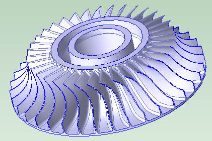
In this case, the geometric property Has Radial Undercut is true for the GCD (as listed in the Geometric Cost Drivers pane):

By default, axisGrooves classified as <Unknown>, as well as those classified as Flutes, are routed to milling processes that are not specific to gear making (specialized gear-making cutting mills and tool paths are not used in this case).
Number of Teeth
This is the total number of gear teeth. For user-defined gears, this defaults to a value that is based on surface diameter. Be sure to enter the correct number of teeth.
PitchDiameter/Tooth Size Radio Buttons
For user-defined gears, do one of the following:
• Select the Input Pitch Diameter radio button to display the Pitch Diameter field. See Pitch Diameter.
Module
Displayed only if the Input Tooth Size radio button is selected. See PitchDiameter/Tooth Size Radio Buttons.
Commonly used for metric-based gears, this field specifies the tooth size, by specifying the number of millimeters of pitch diameter per tooth (that is, pitch diameter in millimeters divided by the number of teeth). Module times Pi is the number of millimeters of circumference (of the pitch circle) per tooth.
If you use this field, the pitch diameter is set to halfway between Min Diameter and Max Diameter (see Min Diameter and Max Diameter).
Pitch Diameter
Displayed only if the Input Pitch Diameter radio button is selected. See PitchDiameter/Tooth Size Radio Buttons.
This field specifies the diameter of a pitch circle. The pitch diameter cannot usually be directly measured on a gear, but it serves as the basis for many calculations. If you use this field, tooth size is the pitch circle circumference (Pi times the pitch diameter) divided by the number of teeth (see Number of Teeth).
A warning is displayed in the dialog if you specify a value that is not between Min Diameter and Max Diameter (see Min Diameter and Max Diameter).
Pitch circle can be defined in terms of pitch surfaces as follows:
• The pitch surfaces of mating gears are the imaginary surfaces that roll together without slipping when the gears turn. Pitch surfaces are cylinders for spur and helical gears, and they are (truncated) cones for bevel gears.

• A pitch circle is formed from the intersection of the gear’s pitch surface and a plane normal the gear’s axis of rotation. If the pitch surface is a cone, the pitch circle is the largest circle formed from the intersection of the gear’s pitch surface and some plane normal the gear’s axis of rotation (that is, the circle that forms the base of the pitch cone).

Note that diametral pitch is the number of teeth per inch of pitch diameter (that is, the number of teeth divided by the pitch diameter in inches). Pi divided by diametral pitch is circular pitch (the arc distance along a pitch circle between corresponding points of adjacent teeth).
aPriori estimates pitch diameter as the halfway diameter between minDiameter and maxDiameter. The User must override this value to get a more accurate dimension.
Face width
For spur and helical gears, this is the width of the gear in the axial direction.

For bevel gears, face width is the width of the gear in the axial direction divided by the cosine of the cone angle.
Pressure Angle
The pressure angle for mating gears is the acute angle between the line of action (the line of force between the gears) and a normal to the line connecting the gear centers.
The default value for this field is 14.5 degrees in aPriori baseline VPEs.
Cone Angle
Displayed only for bevel gears (see Gear Type). One half the apex angle of the gear’s root cone.
The gear’s axis of rotation is the root cone’s axis of symmetry. The surface of the root cone coincides with the bottoms of the tooth valleys.

Helix Angle
Displayed only for helical AxiGrooves.
Acute angle formed by the gear’s helix and the axis of rotation.

Hand of Helix
Displayed only for helical AxiGrooves.
Handedness of helix, right or left.
Spiral Angle
Displayed only for spiral bevel gears.
Acute angle formed by the gear’s spiral and the axis of rotation.
Hand of Spiral
Displayed only for spiral bevel gears.
Handedness of spiral, right or left.
Whole Depth
This is the distance, normal to the axis of rotation, from the root circle to the addendum circle. The root circle lies in a plane normal to the axis of rotation and coincides with the bottoms of the tooth valleys. The Addendum circle lies in a plane normal to the axis of rotation and coincides with the tops of the teeth.

If you modify Whole Depth, you must modify Max Diameter and/or Min Diameter accordingly:
Whole Depth = (Max Diameter – Min Diameter) / 2
See Min Diameter and Max Diameter.
Quality System
Select one of the following:
• AGMA New Standard
• AGMA Old Standard
• DIN
AGMA New Standard is the default quality system for aPriori starting point VPEs.
Users of the Cost Model Workbench can modify the default quality system by modifying CSL in axiGroovePostProcessor.csl in the root cost model. Change
qualitySystem = GearQualitySystem.AGMA_New_Standard
to
qualitySystem = GearQualitySystem.AGMA_Old_Standard
or
qualitySystem = GearQualitySystem.DIN
Quality Level
Specify the required quality level. See Process and Operation Routing and Feasibility for information on how quality level affects process routing.
Possible quality values, from highest quality (top row) to lowest quality (bottom row), are as follows:
AGMA New Standard | AGMA Old Standard | DIN |
A2 | Q15 | 2 |
A3 | Q14 | 3 |
A4 | Q13 | 4 |
A5 | Q12 | 5 |
A6 | Q11 | 6 |
A7 | Q10 | 7 |
A8 | Q9 | 8 |
A9 | Q8 | 9 |
A10 | Q7 | 10 |
A11 | Q6 | 11 |
A12 | Q5 | 12 |
•
Max Diameter
For external gears, this is the diameter of the largest circle (in a plane normal to the axis) that coincides with the tops of the teeth.
For internal gears, this is the diameter of the largest circle (in a plane normal to the axis) that coincides with the bottoms of the tooth valleys.
If you modify this field, you must modify Min Diameter and/or Whole Depth accordingly:
Whole Depth = (Max Diameter – Min Diameter) / 2
See also Min Diameter and Whole Depth.
Min Diameter
For external gears, this is the diameter of the smallest circle (in a plane normal to the axis) that coincides with the bottoms of the tooth valleys.
For internal gears, this is the diameter of the smallest circle (in a plane normal to the axis) that coincides with the tops of the teeth.
If you modify this field, you must modify Max Diameter and/or Whole Depth accordingly:
Whole Depth = (Max Diameter – Min Diameter) / 2
See also Max Diameter and Whole Depth.